A Trio of Robotic Navigational Sensors
For under $100 your robot can know exactly where on earth it’s located. Or precisely what room it’s in within your house (or even what wall or furniture it’s nearby). These include:
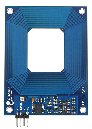
- Radio frequency identification, or RFID uses small transponders that send signals to non-battery powered tags you have mounted on nearby walls or objects. Each tag provides a unique code that identifies itself, and therefore can be used as a kind of beacon system.
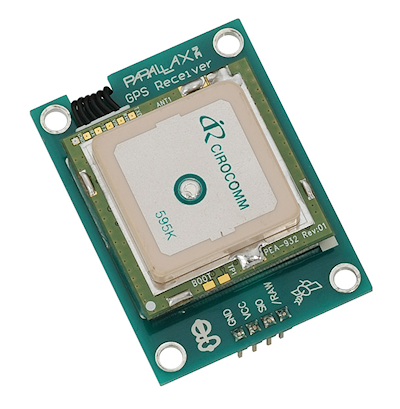
- Global positioning satellite (GPS) is by now a well-known technique using satellites in space to provide location, altitude, even speed information. You can apply the same technology on your robot.
- Gyroscopes sense changes in speed and direction, and provide what’s known as inertial navigation. When coupled with other navigation techniques such as odometry and accelerometers, you robot can keep accurate track of where it is. Gyros (the instrument, not the food) are also used to construct self-balancing bots.
Radio Frequency Identification
RFID stands for radio frequency identification, a kind of sensor that is similar in purpose to barcodes, but is meant to operate over longer distances, even through other objects. (Emplantable biochips, like the kind used for pets—and now people—are miniature RFID units.) RFID uses small devices that radiate a digital signature when exposed to a radio frequency signal. RFID is found in products ranging from toys to employee access cards, to gasoline pump “key fobs” and trucking, to farm animal inventories, automobile manufacturing, and more.
Under the Hood: How RFID Works
A transmitter/receiver, called the interrogator (also the reader, transponder, or host), radiates a low- or medium-frequency carrier RF signal. If it is within range, a passive (unpowered) or active (powered) detector, called a tag or transponder, reradiates (or “backscatters”) the carrier frequency, along with a digital signature that uniquely identifies the device.

RFID systems in use today operate on several common RF bands, including a low-speed 100- to 150-kHz band typified by the TIRIS line from Texas Instruments and a higher 13.5-MHz band. Other products operate in the 900-MHz UHF band and the 2.45- and 5.8-GHz microwave bands.
The tag is composed of an antenna coil along with an integrated circuit. The radio signal provides power when used with passive tags, using well-known RF field induction principles. Inside the integrated circuit are decoding electronics and a small memory. A variety of data transmission schemes are used, including nonreturn to zero, frequency shift keying, and phase shift keying.
Manufacturers of the RFID devices tend to favor one system over another, depending on the intended application. Some data modulation schemes are better at long distances, for example.
Why Use RFID?
How can RFID tags be used in robotics? Here are a couple of ideas. Place them . . .
- on multiple robots that are meant to work together. The robots would be able to identify one another as they came into proximity.
- on people. This would allow a robot, or group of robots, to identify each person.
- along baseboards of rooms or doorjambs. As a robot passes by a tag, it can determine where in a room, even in which room, it is currently located.
It is the last idea that holds much promise for amateur robotics. Navigating a robot within a structure or yard is made even more complicated if there are several rooms or areas that the robot must be kept aware of. RFID tags allow the robot to determine which room or area it is currently occupying, without resorting to more complicated mapping or image recognition.
When used for room identification, RFID tags operate as a kind of lighthouse, orienting the robot as it travels. Besides RFID, there are several other ways to provide active navigation signals to a robot: one is infrared beacons placed strategically in a room or area.
Surprisingly, the advantage of RFID over infrared beacons is that the coverage of the RF signal is naturally limited. This provides a convenient way to differentiate the areas of the house where a robot works and plays.
Memory and Cost
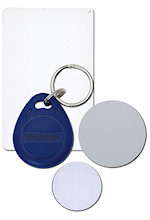
 RFID tags, like those below, have differing amounts of memory, from just a few bytes to several thousand bytes. Most have 32 to 128 bytes—enough to store a serial number, date, and other limited data. For robotics, this is more than enough to serve as room-by-room or locale-by-locale beacons.
While RFID systems are not complex, with few exceptions, cost is not yet in the superaffordable region. Demonstration and developer’s kits are available from some manufacturers in the $200 to $300 range, and this includes the reader and an assortment of tags. Handheld interrogators cost between $150 and $500; the tags cost under $1 each, but most manufacturers want you to buy them in quantities of 250+, making RFID an expensive proposition. However, once implemented, RFID is a carefree and long-term solution to helping your robot know where it is.
Global Positioning Satellite (GPS)
Hovering over the earth are some two dozen satellites that provide accurate world-positioning data to vehicles, ships, and aircraft. The satellite network, referred to as the global positioning system (GPS), works by triangulation: the signals from three or more satellites are received and their timings are compared. The difference in the timings indicates the relative distances between the satellites and the receiver. This provides a “fix” by which the receiver can determine not only the latitude and longitude most anywhere on the earth, but also elevation.
GPS was primarily developed by the U.S. government for various defense systems, but it is also regularly used by private commerce and even consumers. Up until a few years ago, the signals received by a consumer-level GPS receiver have been intentionally “fuzzied” to decrease the accuracy of the device. (This is called selective availability, imposed by the U.S. government for national security reasons.) Instead of the accuracies of a few feet or less that are possible with military-grade GPS receivers, consumer GPS receivers have had a nominal resolution of 100 meters, or about 325 feet.
In practical use, with selective availability activated in the GPS satellites, the actual error is typically 50 to 100 feet. Selective availability has since been deactivated (but could be reactivated in the event of hostilities between the United States and another country), and the resolution of consumer GPS receivers can be under 20 to 25 feet.
GPS modules for robotics use are now quite common, with many under $100. They communicate via standard serial (some I2C) interfaces. Special GPS code libraries are available for microcontrollers such as the Arduino, where you merely connect the GPS unit, let it detect some satellites, then read the serial data for latitude and longitude.

Inertial Navigation with Gyroscopes
Inertial navigation using gyroscopes provide motion data to a robot. Ainertial navigation using a gyroscope employs the same physics that keeps a bicycle upright when its wheels are in motion.
Consider a bicycle wheel spinning in front of you while you hold the axle between your hands. Turn sideways, and the wheel tilts. This is the gyroscopic effect in action; the angle of the wheel is directly proportional to the amount and time you are turning. Put a gyroscope in an airplane or ship, and you can record even imperceptible changes in movement, assuming you are using a precision gyroscope.
Gyros are still used in airplanes today, even with radar, ground controllers, and radios to guide their way. While many modern aircraft have replaced mechanical gyros with completely electronic ones, the concept is the same. During flight, any changes in direction are recorded by the inertial guidance system in the plane (there are three gyros, for all three axes). At any time during the flight, the course of the plane can be scrutinized by looking at the output of the gyroscopes.
Inertial guidance systems for planes, ships, missiles, and other such devices are far, far too expensive for robots. However, there are some low-cost gyros that provide modest accuracies, including gyros originally intended for use in model helicopters. These cost (on average) under $40. They output varying pulses from 1.0 ms to 2.0 ms to indicate rate change.
A better choice is a multiaxis (2D and 3D) angular rate gyroscope. This device is available from numerous online specialty robotics sources. Depending on the device, the output may be a voltage, a PWM pulse, or serial data.

Photos courtesy Parallax Inc.