Build a Piezo Disc Touch Bar
You can build a supersensitive robotic “touch bar” bumper using nothing morethan a couple of commonly available piezo ceramic discs. As shown here, the sensor is constructed with a half-round bar to increase the area of contact. All the parts are available from a variety of local and online retailers.
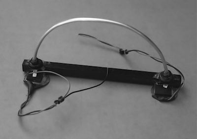
Figure 1 shows a photograph of a finished piezo disc touch bar. The half-round tubing slopes downward slightly. This is intentional, so the robot can adequately sense objects directly in front of it near the ground.

[Figure 1]
Constructing the Piezo Disc Touch Bar
The main sensing elements of the piezo disc touch bar are two 1"-diameter bare piezo ceramic discs. These discs are available at RadioShack and many surplus electronics stores; they typically cost $1 or $2 each, and you can often find them for even less.
- Attach the discs to a 6-1/2"-long support bar, which you can make out of plastic, even a long LEGO Technic beam.
- As shown in Figure 2, glue the discs into place with 1/8"-thick foam (available at most arts and craft stores) so it sticks to the ceramic surface of the disc and acts as a cushion. I used hot-melt glue to speed up construction time.
- Bend a length of 1/8"-diameter solid aluminum tubing (approximately 8" to 9") into a more-or-less half circle. This kind of tubing is commonly found at hobby and craft stores.
- Thread two small grommets through the ends of the tubing, and then glue the grommets to the support bar. Again I used hot-melt glue.
- Flatten the ends of the tubing and bend them at right angles to create “feet”; each foot rests on the foam-padded surface of one of the discs.

[Figure 2]
Building the Interface Circuit
As noted in the previous section, piezo discs are curious creatures. It is the nature of piezoelectric elements to be both consumers and producers of electricity. When the disc is connected to an input, any physical tap or pressure on the disc will produce a voltage. The exact voltage is approximately proportional to the amount of force exerted on the disc: apply a little pressure or tap, and you get a little voltage. Apply a heavier pressure or tap, and you get a bigger voltage.
The piezoelectric material on ceramic piezo discs is so efficient that even a moderately strong force on the disc will produce in excess of 5 or 10 volts.
- That’s good: it makes it easy to interface the discs to a circuit, since there is usually no need to amplify the signal.
- But it’s also bad; the voltage and current from the disc could exceed the maximum inputs of the other electronic device you’re interfacing with. (In fact, pound on a piezo disc with a hammer, and, though it might be broken when you’re done, it will also produce a thousand volts or more.)
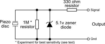
Note the 5.1-volt zener diode shown in Figure 3. This, and the 330 Ω resistor are optional and are included to not only clamp the output of the disc to +5.1 volts (a safe level for most interface circuitry) but also limit the current produced by the disc. In practice, most modern microcontrollers, including the Arduino, already have equivalent protection circuitry built into them, so the extra components may not be required. They don’t alter the operation of the circuit, so add them if you’re not sure.

[Figure 3]
Note that piezoelectric discs also make great capacitors. This means that over time the disc will take a charge, and the charge will show up as a constantly changing voltage at the output of the disc. To prevent this, be sure to insert a resistor across the output of the disc and ground. This resistor bleeds off the excess capacitance.
In my experiments with the specific discs I used, I found that a resistor of about 1 megohm eliminated the charge buildup without excessively diminishing the sensitivity of the disc.
- A higher value will increase sensitivity, but it could cause an extra charge buildup. You probably don’t want, or need, to exceed about 5.6 megohms.
- A lower value will reduce the buildup but also reduce the sensitivity of the disc.
Mounting the Touch Bar
Once you have constructed the piezo disc touch bar and added the voltage-limiting circuitry, you can attach it to the body of the robot. The front of the robot is the likely choice, but you can add additional bars to the sides and rear to obtain a near 360° sensing pattern. The width of the bar makes it ideal for any robot that’s between about 8" and 14" wide.
Since the sensing element of the touch bar, the aluminum tube, has a half-round shape, the sensor is also suitable for mounting on a circular robot base. For added compliancy, you may wish to mount the bar using a thick foam pad, spring, or shock absorber (shocks made for model racing cars work well). If the bar is mounting directly to the robot, the sensor exhibits relatively little compliancy.
You should mount the bar at a height that is consistent with the kinds of objects the robot is most likely to collide with. For a “wall-hugging” robot, for example, you may wish to mount the bar low and ensure that the half-round tube slopes downward. That way, the sensor is more likely to strike the baseboard at the bottom of the wall.
Software For Sensing a Collision
The program touchbar.pde shows a short example program for the Arduino microcontroller for reading the values provided by the piezo disc touch bar. For simplicity, only one of the discs is connected, and it is attached to pin A0 of the Arduino. This allows the pin to be read as an analog signal. The program determines whether the voltage produced by tapping at the disc is over a certain arbitrary threshold (100 out of a possible range of 0 to 1023; 100 is about 10 percent of 5 volts, or an output voltage of 0.5 volts). If it is, then the Arduino’s built-in LED briefly flashes.
touchbar.pde
const int led = 13;
const int threshold = 100;

void setup() {
  pinMode(led, OUTPUT);
  Serial.begin(9600);
}

void loop() {
  int disc = analogRead(A0);
  Serial.println(disc, DEC);
  if(disc>threshold)
    flashLed();
  delay(100);
}

void flashLed() {
  digitalWrite(led, HIGH);
  delay(500);
  digitalWrite(led, LOW);
}