Using Passive Infrared Detection
Passive infrared sensors detect the proximity of humans and animals. These systems, popular in both indoor and outdoor security systems, work by detecting the change in infrared thermal heat patterns in front of a sensor. This sensor uses a pair of pyroelectric elements that react to changes in temperature. Instantaneous differences in the output of the two elements are detected as movement, especially movement by a heat-bearing object, such as a human.
You can purchase pyroelectric sensors—commonly referred to as PIR, for passive infrared—new or salvage them from an existing motion detector. The output of the sensor needs to be amplified, because the voltage levels it produces are low. Because of this, it’s usually easiest and least expensive to use a ready-made PIR module that contains the sensor, the amplifier, and even the plastic focusing lens. Cost is typically $10 to $12, depending on the source.
A Closer Look at Pir Sensors
For the sake of background information, Figure 1 shows a typical three-lead PIR device. Physically, PIR sensors look a lot like old-style transistors and come in metal cans with a dark rectangular window on top.

[Figure 1]
The pinouts are not industry standard, but the arrangement shown in the following table is common: Pin 1 connects to +V (often 5 volts); pin 2 is the output, and pin 3 is ground. Often, a tab or notch will be located near pin 1. PIR sensors typically include an internal FET transistor for preamplification, the power connect and output of the sensor are generally referred to by their common FET transistor pinout names: “drain” and “source”:
| Pin | Name |
1 |
Drain |
2 |
Source |
3 |
Ground |
Using a Pir Module
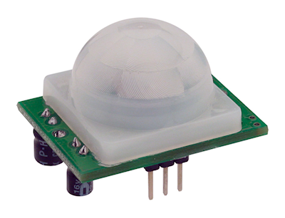
A PIR module is a complete self-contained sensor that you can interface directly to a microcontroller or other circuit. An example is shown in Figure 2. Most have three connector pins: power, ground, and output. The output is a digital LOW or HIGH, depending on whether the sensor has detected movement.

[Figure 2]
- On a single trigger (fleeting motion), the output goes from LOW to HIGH, then to LOW again. The duration of the LOW-HIGH-LOW output change depends on the design of the PIR module.
- On multiple triggers (motion continues), the output continuously toggles between LOW and HIGH.
- Output returns to, and stays at, LOW when all motion has stopped.
While PIR sensors are said to detect thermal energy from living creatures, in fact they are far simpler than that: as previously noted, they merely detect the change in the amount of radiated heat that reaches two parallel elements inside the sensor. This has an impact on how the sensor is used and the things that may trigger it.
For a PIR device to work, the heat source must be in motion. You can stand right in front of the sensor, and the moment you stop moving, it no longer “sees” you. Inversely, the sensor may be triggered by radiated heat that appears to move—flames of a fire, for example, or the momentary glint of sunlight off the windshield of a passing car.
Too, PIR sensors are useless on a moving robot or when attached to a rotating sensor turret. In order to take a reading, the robot must stop. If you use a rotating turret for the sensor, you must temporarily stop it.
PIR devices require a warm-up period in order for the sensing elements to come up to operating temperature. It usually takes a minute or two. During this time, your robot’s control software should disregard any signals from the sensor.
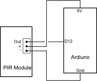
Figure 3 provides an example hookup of a typical PIR module to an Arduino microcontroller. (This PIR module is from Parallax, and is very easy to use.) Program pirsensor.pde shows a simple program for reading the value from the module and displaying it on the Arduino’s built-in LED. Use the pir variable to do something constructive with the value returned from the module. Note that when positively triggered by motion, the Signal line will change for several seconds, even after all motion has ceased.

[Figure 3]
pirsensor.pde
const int signal = 12;
const int led = 13;
int pir = 0;

void setup() {
}

void loop() {
  pir = digitalRead(signal);
  digitalWrite(led, pir);
  delay(200);
}
Using a Focusing Lens
PIR sensors work by detecting electromagnetic radiation in the infrared region, especially about 5 to 15 micrometers (5000 to 15,000 nanometers). Infrared radiation in this part of the spectrum can be focused using simple nonglass optics. While you can use a PIR device without focusing, you’ll find that range and sensitivity are greatly enhanced when you use a lens. Typical maximum distance with a lens over the PIR element is 15 to 20 feet, though more accurate readings are made at distances from 2 to 10 feet.
Motion detectors and PIR modules use a specially designed plastic Fresnel lens to focus infrared radiation. In the case of a motion detector for outdoor security, the lens is a piece of plastic with grooves that gather more light at the top than at the bottom. With this geometry, when the sensor is mounted high and pointing down, the motion detector is more sensitive to movement farther away than right underneath.
If you’ve gotten your PIR sensor by hacking a motion detector, you can use the same Fresnel lens for your robot. You may wish to invert the lens from its usual orientation (because your robot will likely be near the ground, looking up).
Hacking a Motion Detector Board
If you’ve got an outdoor security light with motion detector that you’re not using, you may be able to hack into the motion detector circuit board and use it as an ersatz humanoid detector. Your success depends entirely on the design of the circuit board in the motion detector and how good you are as a hardware hacker!
For best results, use a motion detector unit that is battery-powered. This avoids any possibility that the circuit board in the unit also includes components for rectifying and reducing an incoming AC voltage. If you discover the circuit board is directly wired to the incoming AC line, put the motion detector back together and move on to your next project.
Assuming the circuit board is designed for use with DC power to the board, apply operating voltage to the board. It may be as little as 5 volts, but it could be 9 to 12 volts. Increase the supply voltage as needed to properly operate the board.
Using a multimeter, carefully probe various points on the circuit board and observe the reading on the meter or scope. Wave your hand over the sensor and watch the meter or scope. If you’re lucky, you’ll find either or both of two kinds of useful signals:
- Digital (on/off) output. The output will normally be LOW and will go HIGH when movement is detected. After a brief period (less than 1 second), the output will go LOW again when movement is no longer detected. With this output, you do not need to connect the sensor to an analog-to-digital converter.
- Analog output. The output, which will vary by several volts, is the amplified output of the PIR sensor. With this output, you will need to connect the sensor to an analog-to-digital converter (or an analog comparator).
You may also locate a timed output, where the output will stay HIGH for a period of time—up to several minutes—after movement is detected. This output is not as useful in robotics, but it’s better than nothing.
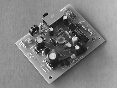
Figure 4 shows the innards of a hacked motion detector. In this model, I found a suitable analog located near a diode; I then soldered a wire to that diode. If the PIR board you are using operates with a 5-vdc supply, you can connect the wire you added directly to a microprocessor or microcontroller input.

[Figure 4]
Use care when poking around inside the motion detector, or you may cause a short circuit that will ruin the board.