Touch Sensitivity with Laser Fiber “Whiskers”
You know about fiber optics: they’re used to transmit hundreds of thousands of phone calls through a thin wire. They’re also used to connect together high-end home entertainment gear and even to make “light sculpture” art.
On their own, optical fibers offer a wealth of technical solutions, and when combined with a laser, optical fibers can do even more. The unique “whiskers” project that follows makes use of a relatively underappreciated synergy between low-grade optical fibers and lasers.
To fully understand what happens to laser light in an optical fiber, let’s first take a brief look at how fiber optics work and then how the properties of laser light play a key role in making the fiber-optic robo-whiskers function.
Fiber Optics: An Introduction
An optical fiber is to light what plastic pipe is to water. Though the fiber is a solid, it channels light from one end to the other. Even if the fiber is bent, the light follows the path of the fiber.
Optical fibers are composed of two basic materials, as illustrated in Figure 1: the core and the cladding. The core is a dense glass or plastic material that light passes through as it travels the length of the fiber. The cladding is a less dense sheath, also of plastic or glass, that serves as a refracting medium. An optical fiber may or may not have an outer jacket, a plastic or rubber insulation used as protection.

[Figure 1]
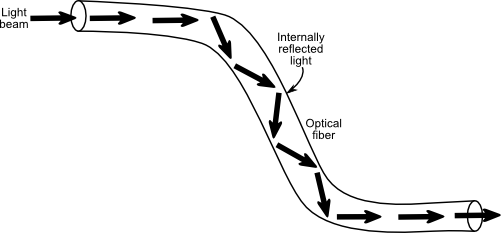
Optical fibers transmit light by total internal reflection (TIR), as shown in Figure 2. The basic idea is that as long as the light beam strikes the cladding at or above a certain angle, it’s reflected on down the fiber.

[Figure 2]
Types of Optical Fibers
The classic optical fiber is made of glass. It tends to be fairly expensive and brittle, but it is an excellent conductor of light. Less expensive optical fibers are made of plastic. Though light loss through plastic fibers is greater than through glass fibers, they are more durable. Both glass and plastic fibers are good conductors of infrared light, which corresponds nicely to common infrared emitters and detectors.
Optical fiber bundles may be coherent or incoherent. These terms relate to the arrangement of the individual strands in the bundle. Coherent bundles are used to transmit whole images, as from a medical endoscope. Expensive stuff! The vast majority of optical fibers are incoherent: any image or particular pattern of light is lost when it reaches the other end of the fiber.
Now, this next part is important: The cladding (the part that reflects light within the fiber) may be one of two types—step-index and graded-index.
- Step-index fibers provide a discrete boundary for the light to travel. Cheaper and easier to manufacture, this type causes a loss of ray coherency when laser light passes through the fiber: that is, coherent laser light going in, a jumbled mess coming out. Normally this is a bad thing, as it reduces the efficiency of the laser beam. But for us, it’s a good thing, as you’ll soon discover.
- There is no discrete refractive boundary in graded-index fibers. The grading, which is more expensive to produce, acts to refract light evenly, at any angle of incidence. Good for telecommunications equipment, not for making laser sensors.
Working with Fiber Optics
Optical fibers may be cut with wire cutters, nippers, or even a knife. When using glass fiber, you must exercise extreme care to avoid injuring yourself from shards of glass that may fly out when the fiber is cut (plastic fibers don’t shatter when cut).
Wear heavy cotton gloves and eye protection when working with optical fibers. Avoid working with fibers around food-serving or preparation areas (that means stay out of the kitchen!). The bits of glass may inadvertently settle on food, plates, or eating utensils and could cause bodily harm.
Building the Laser-Optic Whisker
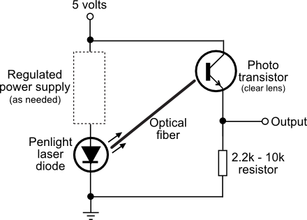
The basics out of the way, let’s begin this project. Consider the arrangement in Figure 3. A laser is pointed at one end of a stepped-index optical fiber. The fiber forms one or more loops around the front, side, or back of the robot.

[Figure 3]
At the opposite end of the fiber is an ordinary phototransistor. When the laser is turned on, the phototransistor registers a certain voltage level from the laser light—say, 2.5 volts. This is the quiescent level—quiescent meaning quiet, at rest.
When one or more of the loops of the fiber are deformed—the robot has touched a person or thing—the laser light passing through the fiber is diverted in its path. With this change, the laser light actually changes pattern, due to interference. All this results in altering the light level reaching the phototransistor.
The change at the output of the phototransistor may be only 1 volt; small difference, but that’s all that’s needed to detect that your robot has touched an object. It’s also enough to measure the relative force of the collision. The more the robot has collided with some object, the more the fibers will deform and the greater the output change of the light as it reaches the phototransistor.
Constructing the Laser-Optic Sensor
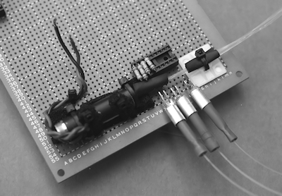
Figure 4 shows a prototype of the laser-optic sensor. It consists of a hacked visible red-light penlight laser, several strands of cheap (very cheap) stepped-index optical fibers from one of those cheesy light fountains, and a set of three clear-lens (no IR filter) phototransistors. Though phototransistors have a peak response in the near infrared—typically about 900 nanometers—they’ll pick up enough of the red emission from the laser, as long as they don’t have built-in infrared filtration.

[Figure 4]
The optical fibers are tied together in a bundle using a small brass collar (cut from tubing available at a hobby store), electrical tape, and a cable tie. This bundle is then inserted into the opening of the penlight laser and held in place with the cable tie.
On the opposite ends of the optical fibers are #18 crimp-type bullet connectors, purchased from an auto parts store. These are designed to splice two #18 or #20 wires together, end to end. I (carefully) crimped them onto the ends of the fibers, so they acted as plug-in connectors.
As shown in Figure 5, these ersatz connectors plug into makeshift “optical jacks,” which are nothing more than 1/4"-diameter by 3/8" aluminum tubing. The tubing is glued over the ends of the phototransistors, and the phototransistors are soldered near the edge of the protoboard.

[Figure 5]
Wiring the Sensor
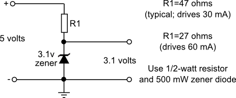
Refer to Figure 6 for a schematic wiring diagram of a power regulator for the penlight laser and connecting the contraption to an Arduino microcontroller. Note the zener diode voltage regulator. The laser I used was powered by two AAA batteries, or roughly 3 volts, so I didn’t need to use a regulated supply. If you use a higher input voltage, be sure to provide regulation. Diode lasers are sensitive to high input voltage, and many will burn out if fed a higher voltage than they are designed for. Many penlight lasers consume 25 to 35 mA at 3 volts, but a few larger ones consume 50 to 60 mA.
Exercise care: too much current will burn out the laser; too little, and the laser won’t actually lase. It’ll still light, but it’ll just be a fancy red LED.

[Figure 6]
The output of a phototransistor is close to the full 0-to-5-volt range of the circuit’s supply range. You’ll want your robot to be able to determine the intensity changes as the whiskers bump against objects.
If you’re using a microcontroller to operate your robot, this means you’ll need to convert the analog signal produced by the detectors into a digital signal suitable for the brains on your bot. Several popular microcontrollers, such as the Arduino, have analog-to-digital converter (ADC) ports built in.
Creating The Whisker Loops
Okay, so the laser-optic whisker system may not use cat-type whiskers with ends that stick out. Still, the word whisker aptly describes the way the system works. If something even so much as brushes lightly against the whisker, the light reaching the photodetector will change, and your robot can react accordingly.
The prototype sensor uses three “whiskers,” all of which were formed into three small loops around the front and two sides of the test robot. I elected to use three so the robot could independently determine in which direction (left, front, right) a collision or bump had occurred.
Don’t make the loops too tight, but neither make them too loose. If they’re too loose, they may wobble or flap while the robot is in motion, giving a false reading.
Getting The Right Kind Of Optical Fiber
Remember that the key to this project is how laser light (not just any kind of light) is transmitted through stepped-index optical fiber. Being the cheapest kind, stepped-index optical fiber is the kind you’ll most often find in “light fountain art,” popular in the early 1970s (and seeing a resurgence today). Don’t use data communications–grade optical fiber—it won’t work.
Before you buy miles of optical fiber, test a 2-foot strand with a suitable diode laser and phototransistor. Loop the fiber and tape it snugly to your desk or workbench. Connect a multimeter to the Output and ground connections of the circuit in Figure 42-28. Dial the meter to read volts. If your meter is not autoranging, select the range just above the 5-volt working voltage of the circuit. You should observe a change of output in the phototransistor as you move the fiber.
Safety and All That: Working with Lasers
Penlight lasers can be easily hacked for a wide variety of interesting robot projects—the soft-touch fiber-optic whisker previously described is just one of them. Penlight lasers use a semiconductor lasing element. While these elements are fairly hardy, they do require certain handling precautions.
And, of course, they emit laser light that can potentially be dangerous to your eyes. So keep the following points in mind:
- Never apply more than the rated voltage or current to the laser, or it will burn up.
- Extend the same care to laser diodes that you do to any static-sensitive device. Wear an antistatic wrist strap while handling it, and use only a grounded soldering pencil when attaching wires to the laser diode terminals. Limit soldering duration to less than 5 seconds per terminal.
- Never connect the probes of a multimeter across the terminals of a laser diode. The current from the internal battery of the meter may damage the laser.
- Don’t look directly into the laser beam even if you can’t see any light coming out (is the diode the infrared type?).
- If you are using a laser from a laser penlight, bear in mind that the penlight casing acts as a heat sink. For this reason, it’s best to keep the laser in the casing.