Build a 12-Servo Hexapod
Using the X-Y joints described in the previous section you can construct a hexapod with 2-DOF legs. The robot uses 12 servos, 2 per leg. Besides the X-Y joints already discussed, and the servos (of course), you need only six simple leg pieces and a base to mount everything on.
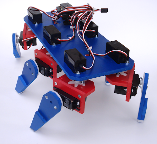
Let’s take a closer look at exactly such a design—we’ll call it the Hex12Bot, to differentiate it from the three-servo design (the Hex3Bot) described earlier in the chapter. The figure below shows a completed 12-servo hexapod, constructed with six X-Y joints. The robot measures 11-1/2" by 7", and stands over 6". Weight with all parts and servos, but no batteries, electronics, or other parts, is 1 pound, 12 ounces.
Because the Hex12Bot uses six independent legs, its walking gait can have many variations. The most common gait and stepping sequence. It’s similar to the gait of the Hex3Bot, except all six legs of the Hex12Bot act as lifters and sweepers.
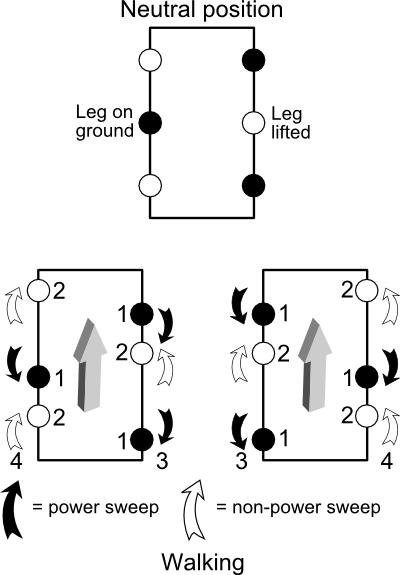
- Lift right or left middle leg. Only one leg is down at any time. The robot tilts to the side opposite the middle leg that is down.
- Power sweep the front/rear legs that are touching the ground. The robot propels forward.\
- Non–power sweep the front/rear legs that are not touching the ground. The robot doesn’t move in this step; it merely positions the legs for the next sequence.
Parts You Need
In addition to six sets of X-Y joints, which were covered in Chapter 27 under “Creating X-Y Servo Joints,” you need the following to complete this project:
- 1 piece of 12" × 12" 6mm-thick expanded PCV (preferred), or 1/4" birch or other hardwood aircraft-grade plywood
- 12 standard-size servo motors. For best results, use servos with a 6-volt torque rating of at least 75 oz-in, and preferably 100 oz-in (about 7.2 kg-cm). Otherwise, the servos may not be able to adequately handle the weight of the robot when walking.
- 12 six-arm (“star”) servo hubs (they usually come with the servo)
- 12 large round servo hubs (they usually come with the servo)
Including the X-Y joints, you need the following to complete the Hex12Bot:
| 12 | #4 × 1/2" sheet metal screws |
48 |
4-40 × 1/2" machine screws |
48 |
4-40 hex nuts |
6 |
Small 1/2" × 1/2" rubber bumper pads (see the furniture pad section at your local hardware store) |
All machine screws are pan or round head.
Cut and Construct the base
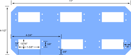
Refer to Figure 1 for the cutting and drilling guide for the base. It measures 11" by 4-1/2". Cutting the puppy can be a little tough because of the six rectangular holes for the servos. Accuracy is a must, or the servos either will not fit properly or will slop around in their pockets.
[Figure 1]
You can simplify construction somewhat by cutting out the servo rectangles at the dotted lines. If you do this, be sure to use four screws and nuts for each servo, to provide adequate strength to the base. You may also want to add a short 3/8" aluminum strip across the opening in order to reinforce it. Secure it in place with 4-40 fasteners.

Cut and Construct the Lower Legs
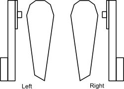
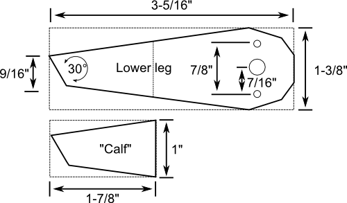
See Figure 2 for the cutting and drilling layout for the six lower legs. For each leg you’ll cut two parts: the leg itself and a smaller “calf” that serves to thicken the bottom of the leg. Use a 1/4" bit for the center hole shown in the cutting and drilling layout.
[Figure 2]
Use 4-40 machine screws and nuts to attach a large round servo hub to the top of each leg. Use glue or cement to attach the calf to the leg.
- When using expanded PVC for the leg material, use PVC solvent cement, available at all hardware and home improvement stores. The cement goes on water-thin and sets up a strong bond in less than a minute.
- When using wood for the leg material, use a good-quality wood glue. Allow at least an hour for the glue to set.
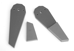 Use medium-grit sandpaper to smooth out the bottom of the legs so there is an even surface. Then apply a self-adhesive 1/2" square rubber pad to the bottom of the leg. This acts as a foot.
Attach Upper Leg Servos
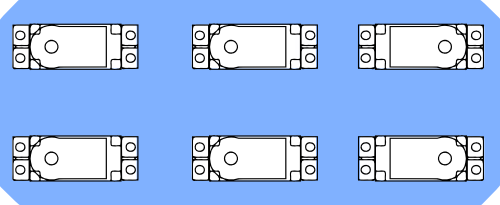
Using 4-40 machine screws and nuts, attach the six servos to the base. Use four screws and nuts for each servo. The body (back side) of the servo is on the top of the base. Note the orientation of the driveshafts for each of the servos, as shown in Figure 3.
[Figure 3]
Construct and Attach X-Y Joints
Following the directions in “Creating X-Y Servo Joints” earlier in this chapter, construct six X-Y joints. Use 4-40 machine screws and nuts to attach a six-arm “star” servo hub to the solid plate of each joint.
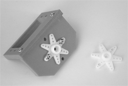
Center all six upper leg servos by slowly rotating their output shafts all the way in one direction, then the other. Return the shaft to the approximate center position.
Use the screw that comes with the servo to attach the X-Y joint to the servo. The bracket side of the joint should face outward.
Attach Lower Leg Servos to X-Y Joints
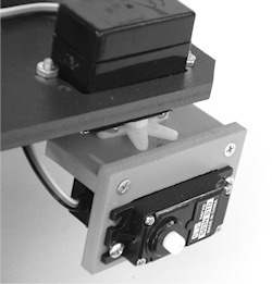 Using 4-40 machine screws and nuts, attach the remaining six servos to the their X-Y joints. Though you’re free to experiment, for now orient the driveshafts of the servos so they are all facing the same end of the robot.
Center all six lower leg servos by slowly rotating their output shafts all the way in one direction, then the other. Return the shaft to the approximate center position.
Attach Lower Legs to Lower Leg Servos
Use the screw that comes with the servo to attach the lower legs to their lower leg servos. Figure 4 shows the underside of the Hex12Bot and the arrangement of the legs on their servos.
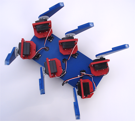
[Figure 4]
Operating the Hex12Bot
Refer to the figure at the top of this app note for the walking gait of the Hex12Bot. You need a microcontroller or serial servo controller to run the Hex12Bot’s servos. A serial servo controller is recommended to offload the demands of operating all those servos from your robot’s microcontroller.
Here is the walking sequence:
- Lower the legs marked #1.
- Lift the legs marked #2.
- Move the #1 legs back. This is a power sweep, and it propels the robot forward.
- Move the #2 legs forward. This is a non–power sweep, and it positions the legs for the next sequence.
- Repeat steps 1 through 4 to continue walking.
You may perform steps 3 and 4 simultaneously. However, for obvious reasons, you must do steps 1 and 2 in order—you cannot lift the legs first, because then all the legs would be lifted.
- To make the robot go in reverse, reverse the direction of the power sweep.
- To make the robot turn, power sweep on one side only.
Figure 5 shows the orientation of the legs and how the two servos work in tandem to move the robot. The upper leg servo sweeps the servo back and forth so that the leg moves about 1" to 3" on the ground. The lower leg servo lifts the leg up or down in order to contact the ground. When the leg is touching the ground, the sweep powers the robot forward or back. When the leg is not touching the ground, the sweep is used to reposition the leg for the next step.
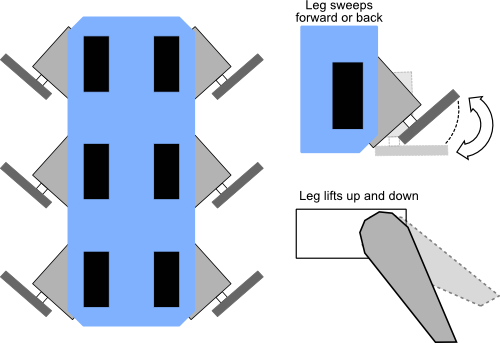
[Figure 5]
Alternative Feet
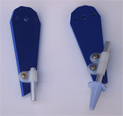 Feel free to augment the Hex12Bot’s legs with alternative feet. One idea is to connect a 1/4"-diameter aluminum rod using a 1/4" cable clamp (these are available at some hardware stores and at online stores that cater to cable management products). Adjust the length of the rod to increase or decrease the height of the foot. Use one or two clamps to hold the foot in place; when using one clamp be sure it’s on real tight or the foot may spin. You can use the cylindrical shape of the foot to fashion unique forms of leg sensors.
A Note About Durability
The Hex12Bot takes some design shortcuts in order to simplify its construction and to make it cheaper to build. As I noted earlier in the chapter, legged robots really benefit from using yoke-style brackets, which support the joints from both the servo shaft and a secondary passive shaft on the other side of the motor.
The Hex12Bot doesn’t use yoke brackets, so there’s extra strain on the servos as they support the weight of the robot. As such, the servos may wear out prematurely, especially if they don’t use ball bearings on the output shaft. (You can decide whether to spend more for hardier servos or get the cheapest ones you can and replace them as needed.)
If you choose, you can also retrofit the X-Y joints to provide a yoke and added support.
Hexapod bots have a tendency to “work themselves loose” because of all the flexing and movement. From time to time get out your screwdriver and wrench and retighten any fasteners that need it. If a sheet metal screw works its way out of an X-Y joint, replace the screw with a longer one (3/4" instead of the 1/2"), dab on some glue to hold it in, or make a new bracket.
Mounting Electronics and Accessories
Like the three-servo robot described earlier in the chapter, the Hex12Bot provides only minimal surface area for placing batteries, electronics, and other components. You’ll probably want to add a second deck to the base of the robot. Use a set of four standoffs at least 1" in length (to clear the body of the servos). You can make the second deck the same size and shape as the first, providing ample area—almost 50" square—for accessories.
Be mindful of excess weight, especially if your servos are a tad underpowered. Use NiCd or NiMH batteries instead of alkaline; they weigh less. Once you have your Hex12Bot constructed and running, experiment with adding some deadweight (lead fishing weights, rocks, whatever) to determine how much you can add to your bot before it begins to stumble.
