Logic Probes 101
A handy tool for testing electronic circuits is the logic probe, so-called because it verifies signals used in logic circuits (anything that deals with digital 0s and 1s, LOWs and HIGHs). These kinds of circuits include microcontrollers. I’ve prepared a free Logic Probe 101 article on the RBB Online Support site (see Appendix A) that provides more information.
Meters are most often used for measuring voltage, current, and other analog (continuously varying) signals. They’re well suited for many kinds of electronic circuits, but falter when it comes to digital (on-or-off) circuits, the kind most robots use for high-speed brains.
Logic probes test for the presence or absence of low-voltage signals that represent digital data. These data, symbolized by the binary numbers 0 and 1, are electrically defined in many circuits as 0 and 5 volts, respectively—though in practice, the actual voltages of the 0 and 1 values depend entirely on the circuit.
While you can sometimes use a multimeter to test a digital circuit, the results aren’t always predictable or accurate. The reason: The data can change more quickly than the multimeter can track. Another kind of inexpensive testing tool, the logic probe, is designed to work around this limitation.
(This doesn’t mean a multimeter is useless in more advanced robots; on the contrary, it just means you need a multimeter and a logic probe.)
How Logic Probes Work
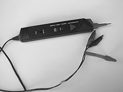
Logic probes are so named because the parts of a circuit that create and consume all those digital 0s and 1s are referred to as logic gates. Models like the one in Figure 1 are low-cost because they are electrically quite simple, because their job is simple: they’re designed to give a visual and (usually) aural cue about the logic state of a particular circuit line.

[Figure 1]
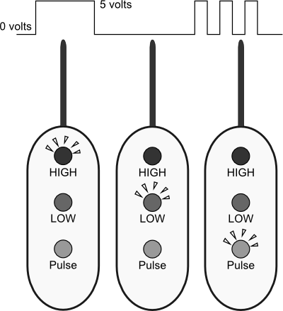
- One LED (light-emitting diode) on the probe lights up if the logic is 0 (also referred to as LOW). See Figure 2.
- Another LED lights up if the logic is 1 (or HIGH).
- A third LED indicates a pulsing signal, one that rapidly alternates between 0 and 1 (or LOW and HIGH if you prefer that nomenclature). A good logic probe can detect a logic gate pulsing at speeds of up to 10 MHz (10 megahertz, or 10,000,000 times per second), which is more than fast enough for most robotics applications, even when using computer control. The minimum detectable pulse width—the time the pulse remains at one level—is 50 nanoseconds, which, again, is more than sufficient. Or put it this way: 50 nanoseconds is 50 billionths of a second, the time it takes light to travel about 50 feet.

[Figure 2]
Most logic probes are not battery operated; rather, they obtain their operating voltage from the circuit under test. You can also make a logic probe on your own if you wish. A number of project books provide plans
Using a Logic Probe
The same safety precautions for using a multimeter apply when you are using a logic probe. Be careful when working close to any kind of high voltage or current. Logic probes aren’t meant for testing these kinds of circuits anyway, so if high voltage or current is exposed in your circuit, cover that portion up so you don’t actually touch it with your fingers or the logic probe.
- Connect the red and black leads of the logic probe to the circuit under test. Red goes to the + (positive) supply, black to the – (negative) supply.
- Touch the tip of the probe to the part in the circuit you want to test (see Figure 30-7). Watch the LEDs on the probe to determine the logic state of that part of the circuit.
To use the logic probe you really have to know what points in the circuit to test. This means you need to have a schematic or other wiring diagram, so you know what goes to where. It’s nearly impossible to blindly use the logic probe on a circuit without knowing what you are testing.