Experiments in Quadrature Encoders
Quadrature encoders are regularly used in robotics to detect and measure movement of the vehicle's drive wheels. Quad encoders are a refinement over single-channel encoders. While they are more difficult to engineer -- quadrature encoders demand more precision in construction -- they provide greater resolution, more immunity to errors caused by noise, and they are capable of detecting changes in wheel or motor direction.
Quadrature Encoding Defined
The name quadrature comes from the four possible output states of the encoder sensor. Rather than just a single pulse indicating a slotted or striped track in a codewheel, quad encoders use a pair of tracks to go through four distinct phases. . .quad means four
The following table summarizes the four possible encoding states as the disc rotates, either counter-clockwise or clockwise. The tracks are labeled Channel A and Channel B.
| Counter-clockwise rotation | ||
Phase |
Channel A |
Channel B |
1 |
0 |
0 |
2 |
0 |
1 |
3 |
1 |
1 |
4 |
1 |
0 |
Clockwise rotation |
||
Phase |
Channel A |
Channel B |
1 |
1 |
0 |
2 |
1 |
1 |
3 |
0 |
1 |
4 |
0 |
0 |
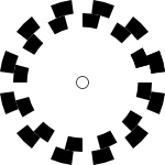
 The “secret” behind quadrature encoding is that the two channels are set apart by 90 degrees. You can see it visually in the figure on the left. There are two sets of stripes, one within the other.
The track on the inside is set apart from the outside track by 90 degrees. This alternating sequence provides the four phases needed for proper quadrature.
As you can imagine, the spacing and arrangement of the tracks are important; misalignment can cause errors. For this reason it's often easiest to use ready-made encoders, which incorporate both the quadrature tracks, and the sensing electronics.
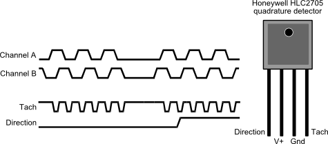
Naturally, quadrature encoders require two sensors, one for each track. The two sensors pick up the pattern changes in their respective tracks, like so:

The order in which the signal change from LOW to HIGH in each channel indicates whether the encoder is rotating clockwise or counter-clockwise. By detecting the order of change you can tell whether the wheels on your robot are spinning forward or backward.
Decoding Quadrature Signals
One method to using a quadrature encoder is to examine the two signals and their timing relationships, and then use this data to provide rotation and direction. Certainly this is possible, but a far easier (and in my opinion superior) approach is to use a ready-made specialty integrated circuit that does all the signal conditioning, processing, pulse counting, and timing. Sounds like an expensive IC, but it's not -- they're routinely under $4, and available in both surface mount and DIP packages.
My favorite is the LS7184, available from US Digital (www.usdigital.com) for about $3.20 each, plus shipping. You need one IC for each encoder on your robot, so if you have two encoders -- one for each wheel -- you need two chips.
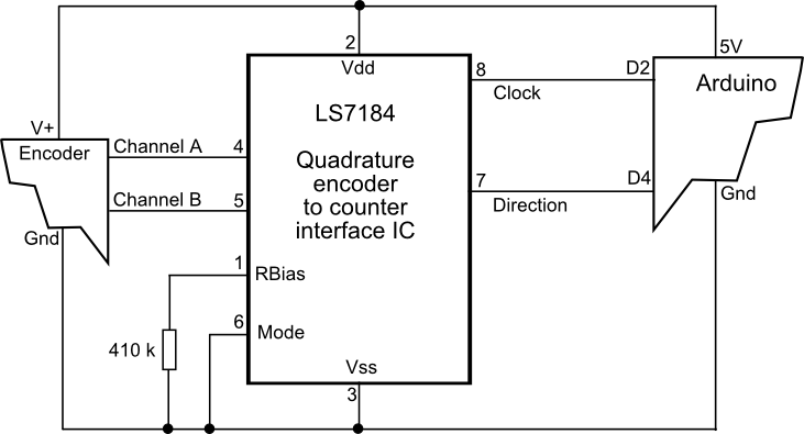
Hookup is easy; see the following schematic for details.

Note the 410 kΩ resistor. This is referred to as RBIAS in the LS7184 datasheet, and it sets the pulse width of the clock output. With a value of 410 kΩ, the pulse width is approximately 6 microseconds, which is definitely long enough for the Arduino to detect the pulse. Smaller values for the RBIAS resistor decrease the pulse width; while higher values increase the pulse width.
I'm showing the LS7184 connected to a quad encoder module, which has electrical connections for +5 volts and ground, plus the outputs for channels A and B. These modules are available from various sources, including US Digital, Lynxmotion, Parallax, and others. I'm also showing the two output lines of the LS7184 -- one is the clock pulse, and the other is the direction indicator -- to an Arduino microcontroller.
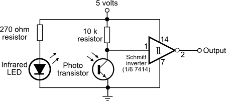
You can also construct your own quad encoder module by printing a two-track disc, and adding your own optical sensing electronics -- infrared LEDs and phototransistors are typical. I suggest conditioning the output of each phototransistor with a Schmitt trigger inverter; this provides a clean transition for each on/off pulse. Experiment with the value of both resistors for best sensitivity. Don't go under 200 ohms for the current limiting resistor above the LED.

Reading the Encoder with an Arduino
Let's assume you've built a quad encoder using the LS7184 IC, and connected it to an Arduino microcontroller development board, as shown in the schematic above. The clock output of the LS7184 provides a pulse for each complete step of the encoder wheel. If the wheel has 32 stripes, for example, you'll get 32 pulses per revolution.
This sketch for the Arduino reads the clock changes on pin D2, which provides for an external interrupt. Each time a clock pulse is detected on this pin, the Arduino immediately branches off to an interrupt routine -- called encoderIntA in the sketch -- to process the pulse.
Code within the interrupt routine examines the instantaneous state of the direction output of the LS7184, which is connected to Arduino pin D4. If the direction is HIGH, the encoder is assumed to be going forward, so the count goes up by one. If the direction is LOW, the encoder is assumed to be going in reverse, so the count goes down by one.
For demonstration purposes the current count value is displayed in the Serial Monitor window. I use an int-size variable to hold the count. This variable can store positive and negative values in the range -32,768 to +32,767. If the count goes above +32,767, it wraps around as a negative value.
If you suspect this might ever happen in your application use a long-size variable instead.
These
store values from -2,147,483,648 to +2,147,483,647. That's a lot of wheel rotations!
/*
  Quadrature encoder example
  Interface to LSI LS7184 quadrature clock converter
  (USDigital part #LFLS7184)

  Demonstrates reading quadrature encoder using Arduino interrupts.
  Clock output is connected to pin 2 (Int0); direction output is
    connected to pin 4.
  Current position is displayed in Serial Monitor window.
*/

const int clkPinA = 2;
const int dirPinA = 4;
volatile int encoderACount = 0;
volatile boolean changeFlag = false;

void setup() {
  Serial.begin(9600);
  pinMode(clkPinA, INPUT);
  pinMode(dirPinA, INPUT);
  attachInterrupt(0, encoderIntA, RISING);
}

void loop() {
 if (changeFlag) {
    changeFlag = false;
    Serial.println(encoderACount);
  }
}

void encoderIntA() {
  if (digitalRead(dirPinA) == HIGH)
    encoderACount++;
  else
    encoderACount--;
  changeFlag = true;
}
Reading from Two Encoders
The beauty of using quad encoder interface ICs is that they already provide separate clock and direction outputs. This is especially useful if you wish to interface two encoders to one Arduino.
The Uno Arduino development board has two external interrupts, Int0 and Int1, located at pins D2 and D3, respectively. Adapting the previous sketch to reliably read two encoders is straightforward, and entails merelyduplicating several lines of code, and renaming the variables that are references.
In the following example the Serial Monitor window displays the channel and current count value for each of two encoders connected to it.
/*
  Dual quadrature encoder example
  Encoder clock outputs are connected to Arduino pins D2
    (Int0) and D3 (Int1) pins.
  Direction outputs are connected to Arduino pins D4 and D5.
*/

const int clkPinA = 2;
const int dirPinA = 4;
const int clkPinB = 3;
const int dirPinB = 5;

volatile int encoderACount = 0;
volatile int encoderBCount = 0;
volatile boolean changeFlagA = false;
volatile boolean changeFlagB = false;

void setup() {
  Serial.begin(9600);
  pinMode(clkPinA, INPUT);
  pinMode(dirPinA, INPUT);
  pinMode(clkPinB, INPUT);
  pinMode(dirPinB, INPUT);
  attachInterrupt(0, encoderIntA, RISING);
  attachInterrupt(1, encoderIntB, RISING);
}

void loop() {
 if (changeFlagA) {
    changeFlagA = false;
    Serial.print("A\t");
    Serial.println(encoderACount);
  }
 if (changeFlagB) {
    changeFlagB = false;
    Serial.print("B\t");
    Serial.println(encoderBCount);
  }
}

void encoderIntA() {
  if (digitalRead(dirPinA) == HIGH)
    encoderACount++;
  else
    encoderACount--;
  changeFlagA = true;
}

void encoderIntB() {
  if (digitalRead(dirPinB) == HIGH)
    encoderBCount++;
  else
    encoderBCount--;
  changeFlagB = true;
}
All-in-One Modules You Can Try
There are a few inexpensive and readily available commercial quadrature encoding modules that incorporate both the sensing optics and the quadrature decoding electronics. One such beast is the Honeywell HLC2705 (about $6.50 from Digikey, part #480-3540-ND). It's designed for use with reflective or transmissive optical discs.
Rather than two separate tracks, the HLC2705 assumes one track, with the stripe pattern set a specific distance apart. The spacing of the two sensors on the device provides the proper 90 degree offset between the two channels. This method is harder to implement because it requires precisely sized stripe patterns to match the expectations of the detector.
Refer to the specification sheet that comes with the sensor for the necessary dimensions and spacings of the stripe pattern. You need to provide your own infrared light source.

As with the LS7184, the Honeywell HLC2705 detector provides a direction and clock (called Tach) output. Connect to the Arduino or other microcontroller in the same fashion as shown for the LS7184, and use an interrupt as demonstrated to accurately count each pulse.