Using Motor Bridges
Bridges allow your robot to control high current motors. They literally "bridge" between the low-current logic circuitry of your robot's brain to the high current demanded from the motors. Many, but not all, use the common "H" arrangement of control circuitry (usually power transistors) to provide on/off and directional controls to the motors -- hence the oft-cited name H-bridge.
Here's a short collection of additional motor bridge ideas you may want to ponder. Some are scratch built, while others rely on commercial bridge circuits.
Relay Bridges
Though often considered "old school," motor bridges using relays solve a number of problems, and easily provide for handling motors demanding many amps of current. Especially when purchased surplus, relays offer a cost-effective means to control your robot's motors.
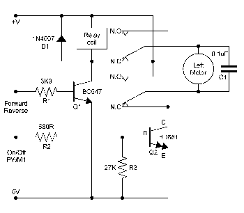
The following two circuits were contributed by robo-maestro Russell Cameron. Circuit 1 is a hybrid solution using a DPDT relay for controlling direction, and a power transistor for on/off control. The transistor can also be driven in low-frequency PWM (pulse width modulation) mode for controlling motor speed.
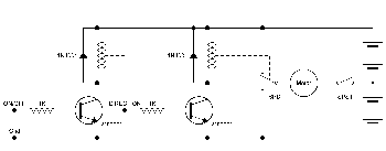
Circuit 2 is a half-bridge using a SPST and SPDT relay and transistor-controlled logic to manage on/off and direction. The bridge requires a split supply (two sets of batteries), and is well-suited for use when driving those small toy motors that are meant for 3V operation. (Like all split-supply drivers, one set of batteries may deplete faster than the other, depending on the driving habits of your 'bot.)
Click on the thumbnail image to see the schematic in full size.
Relay Circuit 1
Relay Circuit 2
L298 Motor H-Bridge
A very popular and reasonably priced all-in-one H-bridge motor control IC is the L298. It can control two motors, not just one. It can handle 2 amps per motor, though to get the maximum current be sure to add a heat sink. The L298 has a large cooling flange with a hole in it, making it easy to attach a homebrew metal heat sink to it.
If there’s a downside to the L298 it’s that it comes in a special “Multiwatt 15” package, with 15 offset pins that don’t match the standard 0.100" spacing of breadboards. But with care, the pins can be rebent as needed. Or you may prefer to simply get a breakout board for the L298, which is a small circuit board with holes drilled in it to accept the chip. You then plug the breakout board into your breadboard. Problem solved.
The schematic below shows a basic connection diagram for controlling two motors using the L298 motor bridge IC. There are three input pins for each motor: Input1, Input2, and Enable1 controls Motor1. Input3, Input4, and Enable2 controls Motor2.
The motors connect to Output1/Output2 and Output3/Output4, as shown.
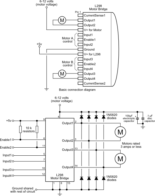
The L298 uses two different supply voltages. The voltage on pin 9 powers the chip itself and should be 5 volts. The voltage on pin 4 supplies the motors, and it can be up to 46 volts.
Let’s look at how to control just one of the motors, Motor1. In order to activate the motor, the Enable1 line must be HIGH. You then control the motor and its direction by applying a LOW or HIGH signal to the Input1 and Input2 lines, as shown in this table.
Input1 |
Input2 |
Action |
LOW |
LOW |
Motor breaks and stops* |
HIGH |
LOW |
Motor turns forward |
LOW |
HIGH |
Motor turns backward |
HIGH |
HIGH |
Motor breaks and stops* |
* To coast a motor to a slower stop, apply a LOW signal to the Enable1 line.
The L298 does not have built-in protection diodes, so you’ll need to add those. The datasheet for the L298 specifies “fast recovery” 1-amp diodes; an inexpensive selection is the 1N4933, available from most online electronic parts outlets.
The chip needs several other external parts for proper operation. Because of the added complexity of using the L298, frankly, most folks opt to get a fully integrated module based on the chip. Most of these are in kit form, so soldering is required, but they’re much easier (and often cheaper) to use than collecting and assembling all the parts yourself.
Using an L298 Motor Board
As noted above, the L298 is one of the more popular bridge modules to use on fully-developed commercial motor control boards. For example, the Dual H-Bridge board, from Seeedstudio, contains the L298 bridge on a heat sink, flyback diodes, screw terminals, indicator LEDs, and other parts on a compact printed circuit board.
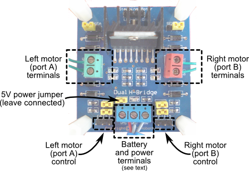
The Seeedstudio L298 board uses separate "A" and "B" inputs for each motor, as defined in the truth table in the previous section. You use the enable pins to control the on/off action of each motor, and then operate the direction of the motors by bringing the A/B inputs HIGH or LOW. This logic steering can be done using discrete circuitry, as shown in the following.
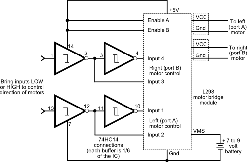
Note this diagram shows the Enable pins tied HIGH, which means the motors are always turned on. This is merely for the sake of demonstration.
Likewise, the board is easy to connect to a microcontroller such as an Arduino. In the following schematic an Arduino uses the A/B inputs for each motor; the enable lines are held high. By changing each A/B input according to the truth table the motors are controlled to stop, start, and change directions.
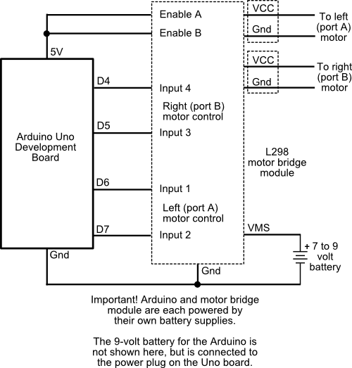
For example:
digitalWrite(6, LOW);
digitalWrite(7, LOW);
Brings the left motor to a stop, while
digitalWrite(6, HIGH);
digitalWrite(7, LOW);
makes the motor turn forward, and
digitalWrite(6, LOW);
digitalWrite(7, HIGH);
turns the motor the other way.
Using a Motor Shield with the Arduino
A popular method of controlling motors with the Arduino is to use a motor shield, such as the SparkFun ArduMoto. This shield likewise is outfitted with an L298 bridge chip. Operation of the bridge is a bit different than the above, as the A/B inputs already have their own logic steering. You instead control each motor by setting a direction pin, and by making a PWM input line HIGH or LOW. The PWM input uses the Enable line for each motor, allowing you to control the speed of the motor was well as whether it is simply on or off.
Logic connection to the ArduMoto is already made for you when you plug in the shield to your Arduino. The motor has its own high current power input (you can use the Vin connection from the Arduino if the supply is of sufficient current to also operate the motors). Separate high-current terminals are provided for each motor.
To control a motor you use code like this:
digitalWrite(3, HIGH);   // PWM (enable) for motor A
digitalWrite(12, LOW);   // Direction
To change direction you use:
digitalWrite(12, HIGH);
The speed of the motor may be set by using the analogWrite function, and selecting a value from 0 (motor stopped) to 255 (motor full speed).
analogWrite(3, 127); // Sets PWM to half
The analogWrite function uses pulse width modulation (PWM) to alter the speed of the motor. In PWM the duty cycle -- the ratio of on versus off times -- controls how fast the motor spins. Given an analogWrite value of 127, the PWM duty cycle is 50%.
Note that PWM duty-cycles DO NOT equate to motor speed. Though 127 is half-way between 0 and 255, and may suggest half speed, the response from any given motor is not linear. At 50% PWM most small DC motors may barely turn, and if they do, they'll exhibit reduced torque and won't be able to move the robot. You need to experiment with the duty cycles to determine the ideal settings for changing the speed on your robot's motors.
Using a Serial Motor Bridge
A serial motor bridge uses asynchronous serial communications to control one or more motors. They're handy when you want to off-load the motor control functions from your microcontroller -- for example, if you're robot is already using all the available I/O pins, or you can't (or don't want to) use the PWM feature of your controller to alter the motor speed.
One of my favorite serial motor bridges is the Pololu Qik 2s9v1. This tiny board operates a pair of 1A motors,
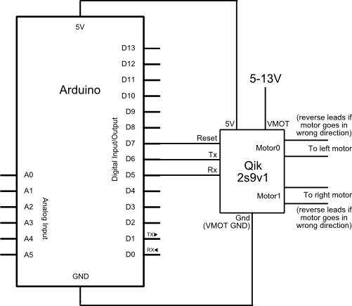
The 2s9v1 comes with a handy Arduino-compatible library that provides the full functionality of the board without having to directly deal with serial commands (though the commands are not difficult to master).
The following sketch (compatible with Arduino 0023 and earlier pre-release versions of the IDE) demonstrate simple forward and back movement of both motors.
#include<CompactQik2s9v1.h> // From pololu.com #include <NewSoftSerial.h> // From arduiniana.org #define rxPin 5 #define txPin 6 #define rstPin 7 NewSoftSerial mySerial = NewSoftSerial(rxPin, txPin); CompactQik2s9v1 motor = CompactQik2s9v1(&mySerial,rstPin); void setup() { mySerial.begin(9600); motor.begin(); motor.stopBothMotors(); } void loop() { // Both motors forward doDelay(); motor.motor0Forward(127); // Left motor motor.motor1Forward(127); // Right motor delay (2000); // Both motors reverse doDelay(); motor.motor0Reverse(127); motor.motor1Reverse(127); delay (2000); } void doDelay() { // Short delay between transistions motor.motor0Forward(0); motor.motor1Forward(0); delay (250); }
Motor Bridges from Around the Web
There are many other motor bridge implementations available on the Web, some better than others. Here are a few of the more notable ones that I like (if you have your favorites please pass them along):
Bob Blick's homebrew 5 amp bridge
Chuck McManis' famous bipolar bridge
FET-based H-bridge circuit and examples
