Switching Voltage Regulation
Linear regulators take an incoming voltage and clamp it to some specific value. Linear regulation isn’t very efficient; as the voltage is stepped down to its desired level, excess energy (the difference between the input voltage and output voltage) is wasted in the form of heat.
In AC-operated circuits this inefficiency is marginal, but it’s particularly notable in battery-powered systems, where battery life is limited.
Too, most linear regulators require a voltage source several volts higher than the expected output voltage. The difference is called voltage drop, and it’s why you need at least 7 volts to power a 5-volt circuit.
An alternative to linear regulators is the switching (or switching-mode) voltage regulator, which is more expensive but more efficient. Most high-tech electronics equipment uses switching power supplies. They’re common and not frightfully expensive.
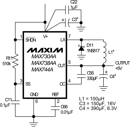
A good example of a step-down switching voltage regulator is the MAX738, from Maxim. It comes in an 8-pin dual inline pin (DIP) IC package, among others; the DIP package is ideal for homebrew circuits. With just a few added parts you can build a simple, compact, and efficient voltage regulator. The output voltage is dependent on the external components that you use.
Refer to the datasheet for the MAX738 for sample circuits. A typical circuit for a 5-volt supply, copied from the MAX738’s datasheet, is shown here. The circuit can handle up to 750 mA. Component values are those provided by the datasheet.

All the external components are standard fare, except for the inductor. Inductors—also called coils or chokes—are common in radio circuits, but not as much in digital or analog circuits for robotics. The inductor is rated at 100 μH (μH for microhenrys), and is available at RadioShack and many other online electronics outlets.