ArdBot Expandable Robot Platform
View the main ArdBot page here
Errata
Parts 1 and 2
- Uno, not Duo. During writing of the first articles I heard about the new Arduino about to come out, and got the new name from a blog posting. Turns out the name was wrong. During editing some of the references to the "Arduino Duo" were not caught.
Part 3
- 90 stops the servo. Under the section "More Experiments with Servo Objects" there are references to using the myServo.write method with a value of 0 to stop the servo. The correct value, of course, is 90.
Part 5
Sharp Infrared Proximity Sensor Redux (Part 5)
The fifth installment of Making Robots with the Arduino includes a circuit that demonstrated a method of depowering the ArdBot's Sharp infrared proximity detector. The purpose of the circuit was to to conserve power when the sensor is not in use.
As I've refined the Ardbot's software I've determined the method is not necessary, and in fact, is counter-productive. It turns out that in practice it slows things down considerably, and introduces as much signal noise as it eliminates.
Decreased Speed
The Sharp datasheets talk about requiring about 40 milliseconds (ms) for the output of the sensor to stabilize before you can take the first reading after the sensor is first powered on. In my recent trials I discovered the sensor will sometimes provide highly erroneous results after just being switched on, even after waiting the recommended 40ms. After testing several sensors, it turns out you need a lot more than 40ms -- often 250ms and higher -- in order to assure accurate results for the first reading.
Plus, for improved accuracy it's a good idea to take successive "snapshots," each spaced a sufficient time apart to ensure a completely separate reading from the sensor. Assuming five snapshots, spaced about 50ms apart, that's an additional 250ms, for a total delay of 500ms, or half a second. Not good.
Increased Signal Noise
I wouldn't have expected it, but the addition of the transistor to turn the Sharp sensor on and off actually increased the noise appearing on the output of the sensor. I suspect this is due to the transistor picking up the switching noise induced by the sensor each time it takes a reading. The 1μF capacitor across the output and ground of the sensor filters a lot of the extra noise out.
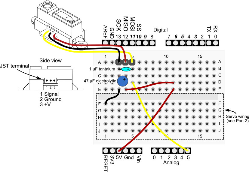
In the revised circuit (see below) I've kept the 1μF cap to help integrate multiple readings (and reduce spurious values), and also added a 47μFelectrolytic capacitor on the solderless breadboard. This cap was mentioned in the text of Part 5, but was not explicitly indicated in the circuit drawing. It is now.
Revised Circuit and Demonstration Sketch
Use these new circuit diagrams for connecting the Sharp analog infrared sensor to the ArdBot. Click on an image for a larger view (opens a new window).
Download the revised sketch for Part 5.
Part 6
- Left is right (and right is left). On page 38 under "Constructing a Two-Sensor Line Follower," the logic for the left and right sensors is reversed. It should read: "If the right sensor doesn't detect the line, it means the robot has veered to far to the right. To compensate, the robot steers back over to the left."
- In the gap. In the sidebar on page 39 the ideal maximum gap is 1/4", not 1/84".

